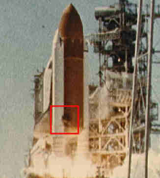
Just after liftoff at .678 seconds into the flight, photographic data
show a strong puff of gray smoke was spurting from the vicinity of the
aft field joint on the right Solid Rocket Booster.  The two pad 39B
cameras that would have recorded the precise location of the puff were
inoperative.  Computer graphic analysis of film from other cameras
indicated the initial smoke came from the 270 to 310-degree sector of
the circumference of the aft field joint of the right Solid Rocket
Booster.  This area of the solid booster faces the External Tank.  The
vaporized material streaming from the joint indicated there was not
complete sealing action within the joint.
 (NASA PICTURE -EDITED BY TSE)
Eight more distinctive puffs of increasingly blacker smoke were
recorded between .836 and 2.500 seconds. The smoke appeared to puff
upwards from the joint. While each smoke puff was being left behind
by the upward flight of the Shuttle, the next fresh puff could be seen
near the level of the joint. The multiple smoke puffs in this
sequence occurred at about four times per second, approximating the
frequency of the structural load dynamics and resultant joint
flexing. Computer graphics applied to NASA photos from a variety of
cameras in this sequence again placed the smoke puffs' origin in the
270- to 310-degree sector of the original smoke spurt.
As the Shuttle increased its upward velocity, it flew past the
emerging and expanding smoke puffs. The last smoke was seen above the
field joint at 2.733 seconds.
The black color and dense composition of the smoke puffs suggest that
the grease, joint insulation and rubber O-rings in the joint seal were
being burned and eroded by the hot propellant gases.
At approximately 37 seconds, Challenger encountered the first of
several high-altitude wind shear conditions, which lasted until about
64 seconds. The wind shear created forces on the vehicle with
relatively large fluctuations. These were immediately sensed and
countered by the guidance, navigation and control system.
The steering system (thrust vector control) of the Solid Rocket
Booster responded to all commands and wind shear effects. The wind
shear caused the steering system to be more active than on any
previous flight.
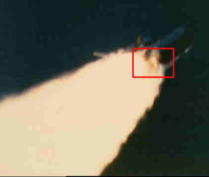
Both the Shuttle main engines and the solid rockets operated at
reduced thrust approaching and passing through the area of maximum
dynamic pressure of 720 pounds per square foot. Main engines had been
throttled up to 104 percent thrust and the Solid Rocket Boosters were
increasing their thrust when the first flickering flame appeared on
the right Solid Rocket Booster in the area of the aft field joint.
This first very small flame was detected on image enhanced film at
58.788 seconds into the flight. It appeared to originate at about 305
degrees around the booster circumference at or near the aft field
joint.
 (NASA PICTURE -EDITED BY TSE)
One film frame later from the same camera, the flame was visible
without image enhancement. It grew into a continuous, well-defined
plume at 59.262 seconds. At about the same time (60 seconds),
telemetry showed a pressure differential between the chamber pressures
in the right and left boosters. The right booster chamber pressure
was lower, confirming the growing leak in the area of the field joint.
As the flame plume increased in size, it was deflected rearward by the
aerodynamic slipstream and circumferentially by the protruding
structure of the upper ring attaching the booster to the External
Tank. These deflections directed the flame plume onto the surface of
the External Tank. This sequence of flame spreading is confirmed by
analysis of the recovered wreckage. The growing flame also impinged
on the strut attaching the Solid Rocket Booster to the External Tank.
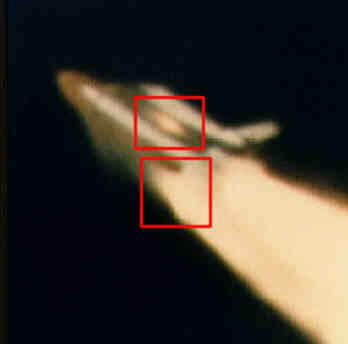
The first visual indication that swirling flame from the right Solid
Rocket Booster breached the External Tank was at 64.660 seconds when
there was an abrupt change in the shape and color of the plume. This
indicated that it was mixing with leaking hydrogen from the External
Tank. Telemetered changes in the hydrogen tank pressurization
confirmed the leak. Within 45 milliseconds of the breach of the
External Tank, a bright sustained glow developed on the black-tiled
underside of the Challenger between it and the External Tank.
 (NASA PICTURE -EDITED BY TSE)
Beginning at about 72 seconds, a series of events occurred extremely
rapidly that terminated the flight.  Telemetered data indicate a wide
variety of flight system actions that support the visual evidence of
the photos as the Shuttle struggled futilely against the forces that
were destroying it.

At about 72.20 seconds the lower strut linking the Solid Rocket
Booster and the External Tank was severed or pulled away from the
weakened hydrogen tank permitting the right Solid Rocket Booster to
rotate around the upper attachment strut.  This rotation is indicated
by divergent yaw and pitch rates between the left and right Solid
Rocket Boosters.

At 73.124 seconds,. a circumferential white vapor pattern was observed
blooming from the side of the External Tank bottom dome.  This was the
beginning of the structural failure of hydrogen tank that culminated
in the entire aft dome dropping away.  This released massive amounts
of liquid hydrogen from the tank and created a sudden forward thrust
of about 2.8 million pounds, pushing the hydrogen tank upward into the
intertank structure.  At about the same time, the rotating right Solid
Rocket Booster impacted the intertank structure and the lower part of
the liquid oxygen tank.  These structures failed at 73.137 seconds as
evidenced by the white vapors appearing in the intertank region.
Within milliseconds there was massive, almost explosive, burning of
the hydrogen streaming from the failed tank bottom and liquid oxygen
breach in the area of the intertank.

At this point in its trajectory, while traveling at a Mach number of
1.92 at an altitude of 46,000 feet, the Challenger was totally
enveloped in the explosive burn.  The Challenger's reaction control
system ruptured and a hypergolic burn of its propellants occurred as
it exited the oxygen-hydrogen flames.

  The reddish brown colors of the
hypergolic fuel burn are visible on the edge of the main fireball.
The Orbiter, under severe aerodynamic loads, broke into several large
sections which emerged from the fireball.  Separate sections that can
be identified on film include the main engine/tail section with the
engines still burning, one wing of the Orbiter, and the forward
fuselage trailing a mass of umbilical lines pulled loose from the
payload bay.

STS 51-L SEQUENCE OF MAJOR EVENTS
Mission Time                                  Elapsed
GMT (hr:min:sec)     Event                  Time (secs.)  Source
16:37:53.444  ME-3  Ignition Command              -6.566  GPC
   37:53.564  ME-2  Ignition Command              -6.446  GPC
   37:53.684  ME-1  Ignition Command              -6.326  GPC
   38:00.010  SRM Ignition Command (T=0)           0.000  GPC
   38:00.018  Holddown Post 2 PIC firing           0.008  E8 Camera
   38:00.260  First Continuous Vertical Motion     0.250  E9 Camera
   38:00.688  Confirmed smoke above field joint
              on RH SRM                            0.678  E60 Camera
   38:00.846  Eight puffs of smoke (from 0.836
                thru 2.500 sec MET)                0.836  E63 Camera
   38:02.743  Last positive evidence of smoke
              above right aft SRB/ET attach ring   2.733  CZR-1 Camera
   38:03.385  Last positive visual indication
                  of smoke                         3.375  E60 Camera
   38:04.349  SSME 104% Command                    4.339  E41M2076D
   38:05.684  RH SRM pressure 11.8 psi above
                nominal                            5.674  B47P2302C
   38:07.734  Roll maneuver initiated              7.724  V90R5301C
   38:19.869  SSME 94% Command                    19.859  E41M2076D
   38:21.134  Roll maneuver completed             21.124  VP0R5301C
   38:35.389  SSME 65% Command                    35.379  E41M2076D
   38:37.000  Roll and Yaw Attitude Response to
              Wind (36.990 to 62.990 sec)         36.990  V95H352nC
   38:51.870  SSME 104% Command                   51.860  E41M2076D
   38:58.798  First evidence of flame on RH SRM   58.788  E207 Camera
   38:59.010  Reconstructed Max Q (720 psf)       59.000  BET
   38:59.272  Continuous well defined plume
                    on RH SRM                     59.262  E207 Camera
   38:59.763  Flame from RH SRM in +Z direction
              (seen from south side of vehicle)   59.753  E204 Camera
   39:00.014  SRM pressure divergence (RH vs. LH) 60.004  B47P2302
   39:00.248  First evidence of plume deflection,
                intermittent                      60.238  E207 Camera
   39:00.258  First evidence of SRB  plume
              attaching to ET ring frame          60.248  E203 Camera
   39:00.998  First evidence of plume deflection,
               continuous                         60.988  E207 Camera
   39:01.734  Peak roll rate response to wind     61.724  V90R5301C
   39:02.094  Peak TVC response to wind           62.084  B58H1150C
   39:02.414  Peak yaw response to wind           62.404  V90R5341C
   39:02.494  RH outboard elevon actuator hinge
               moment spike                       62.484  V58P0966C
   39:03.934  RH outboard elevon actuator delta
                pressure change                   63.924  V58P0966C
   39:03.974  Start of planned pitch rate
                maneuver                          63.964  V90R5321C
   39:04.670  Change in anomalous plume shape
              (LH2 tank leak near 2058 ring
              frame)                              64.660  E204 Camera
   39:04.715  Bright sustained glow on sides
               of ET                              64.705  E204 Camera
   39:04.947  Start SSME gimbal angle large
                pitch variations                  64.937  V58H1100A
   39:05.174  Beginning of transient motion due
                to changes in aero forces due to
                plume                             65.164  V90R5321C
   39:06.774  Start ET LH2 ullage pressure
               deviations                         66.764  T41P1700C
   39:12.214  Start divergent yaw rates
               (RH vs. LH SRB)                    72.204  V90R2528C
   39:12.294  Start divergent pitch rates
               (RH vs. LH SRB)                    72.284  V90R2525C
   39:12.488  SRB major high-rate actuator
                command                           72.478  V79H2111A
   39:12.507  SSME roll gimball rates 5 deg/sec   72.497  V58H1100A
   39:12.535  Vehicle max +Y lateral
               acceleration (+.227 g)             72.525  V98A1581C
   39:12.574  SRB major high-rate actuator
              motion                              72.564  B58H1151C
   39:12.574  Start of H2 tank pressure decrease
              with 2 flow control valves open     72.564  T41P1700C
   39:12.634  Last state vector downlinked       72.624 Data reduction
   39:12.974  Start of sharp MPS LOX inlet
              pressure drop                       72.964  V41P1330C
   39:13.020  Last full computer frame of TDRS
                 data                            73.010 Data reduction
   39:13.054  Start of sharp MPS LH2 inlet
              pressure drop                       73.044  V41P1100C
   39:13.055  Vehicle max -Y lateral
                accelerarion (-.254 g)            73.045  V98A1581C
   39:13.134  Circumferential white pattern on
              ET aft dome (LH2 tank failure)      73.124  E204 Camera
   39:13.134  RH SRM pressure 19 psi lower
              than LH SRM                         73.124  B47P2302C
   39:13.147  First hint of vapor at intertank    E207 Camera
   39:13.153  All engine systems start responding
              to loss of fuel and LOX inlet
                pressure                          73.143  SSME team
   39:13.172  Sudden cloud along ET between
              intertank and aft dome              73.162  E207 Camera
   39:13.201  Flash between Orbiter & LH2 tank    73.191  E204 Camera
   39:13.221  SSME telemetry data interference
              from 73.211 to 73.303               73.211
   39:13.223  Flash near SRB fwd attach and
               brightening of flash between
               Orbiter and ET                     73.213  E204 Camera
   39:13.292  First indication intense white
              flash at SRB fwd attach point       73.282  E204 Camera
   39:13.337  Greatly increased intensity of
               white flash                        73.327  E204 Camera
   39:13.387  Start RCS jet chamber pressure
                fluctuations                      73.377  V42P1552A
   39:13.393  All engines approaching HPFT
              discharge temp redline limits       73.383  E41Tn010D
   39:13.492  ME-2 HPFT disch. temp Chan. A vote
             for shutdown; 2 strikes on Chan. B   73.482  MEC data
   39:13.492  ME-2 controller last time word
                update                            73.482  MEC data
   39:13.513  ME-3 in shutdown due to HPFT discharge
              temperature redline exceedance      73.503  MEC data
   39:13.513  ME-3 controller last time word
                 update                           73.503  MEC data
   39:13.533  ME-1 in shutdown due to HPFT discharge
              temperature redline exceedance      73.523  Calculation
   39:13.553  ME-1 last telemetered data point    73.543  Calculation
   39:13.628  Last validated Orbiter telemetry
              measurement                         73.618  V46P0120A
   39:13.641  End of last reconstructured data
              frame with valid synchronization
              and frame count                    73.631 Data reduction
   39:14.140  Last radio frequency signal from
                Orbiter                          74.130 Data reduction
   39:14.597  Bright flash in vicinity of Orbiter
                nose                             74.587  E204 Camera
   39:16.447  RH SRB nose cap sep/chute
                deployment                       76.437  E207 Camera
   39:50.260  RH SRB RSS destruct               110.250  E202 Camera
   39:50.262  LH SRB RSS destruct               110.252  E230 Camera

ACT POS -- Actuator Position
APU     -- Auxilixary Power Unit
BET     -- Best Estimated Trajectory
CH      -- Channel
DISC    -- Discharge
ET      -- External Tank
GG      -- Gas Generator
GPC     -- General Purpose Computer
GMT     -- Greenwich Mean Time
HPFT    -- High Pressure Fuel Turbopump
LH      -- Lefthand
LH2     -- Liquid Hydrogen
LO2     -- Liquid Oxygen (same as LOX)
MAX Q   -- Maximum Dynamic Pressure
ME      -- Main Engine (same as SSME)
MEC     -- Main Engine Controller
MET     -- Mission Elapsed Time
MPS     -- Main Propulsion System
PC      -- Chamber Pressure
PIC     -- Pyrotechnics Initiator Controller
psf     -- Pounds per square foot
RCS     -- Reaction Control System
RGA     -- Rate Gyro Assembly
RH      -- Righthand
RSS     -- Range Safety System
SRM     -- Solid Rocket Motor
SSME    -- Space Shuttle Main Engine
TEMP    -- Temperature
TVC     -- Thrust Vector Control

NOTE:  The Shuttle coordinate system used is relative to the Orbiter,
as follows:
+X direction = forward (tail to nose)
-X direction = rearward (nose to tail)
+Y direction = right (toward the right wing tip)
-Y direction = left (toward the left wing tip)
+Z direction = down
-Z direction = up
THE CAUSE OF THE ACCIDENT
(Source:  The Presidential Commission on the Space Shuttle Challenger
Accident Report, June 6, 1986)

THE CAUSE OF THE ACCIDENT
The consensus of the Commission and participating investigative
agencies is that the loss of the Space Shuttle Challenger was caused
by a failure in the joint between the two lower segments of the right
Solid Rocket Motor.  The specific failure was the destruction of the
seals that are intended to prevent hot gases from leaking through the
joint during the propellant burn of the rocket motor.  The evidence
assembled by the Commission indicates that no other element of the
Space Shuttle system contributed to this failure.
In arriving at this conclusion, the Commission reviewed in detail all
available data, reports and records; directed and supervised numerous
tests, analyses, and experiments by NASA, civilian contractors and
various government agencies; and then developed specific scenarios and
the range of most probable causative factors.
FINDINGS
1.  A combustion gas leak through the right Solid Rocket Motor aft
field joint initiated at or shortly after ignition eventually weakened
and/or penetrated the External Tank initiating vehicle structural
breakup and loss of the Space Shuttle Challenger during STS Mission
51-L.
2. The evidence shows that no other STS 51-L Shuttle element or the
payload contributed to the causes of the right Solid Rocket Motor aft
field joint combustion gas leak.  Sabotage was not a factor.
3.  Evidence examined in the review of Space Shuttle material,
manufacturing, assembly, quality control, and processing on
non-conformance reports found no flight hardware shipped to the launch
site that fell outside the limits of Shuttle design specifications.
4.  Launch site activities, including assembly and preparation, from
receipt of the flight hardware to launch were generally in accord with
established procedures and were not considered a factor in the
accident.
5. Launch site records show that the right Solid Rocket Motor segments
were assembled using approved procedures.  However, significant
out-of-round conditions existed between the two segments joined at the
right Solid Rocket Motor aft field joint (the joint that failed).
  a. While the assembly conditions had the potential of generating
debris or damage that could cause O-ring seal failure, these were not
considered factors in this accident.
  b. The diameters of the two Solid Rocket Motor segments had grown as
a result of prior use.
  c. The growth resulted in a condition at time of launch wherein the
maximum gap between the tang and clevis in the region of the joint's
O-rings was no more than .008 inches and the average gap would have
been .004 inches.
  d. With a tang-to-clevis gap of .004 inches, the O-ring in the joint
would be compressed to the extent that it pressed against all three
walls of the O-ring retaining channel.
  e. The lack of roundness of the segments was such that the smallest
tang-to-clevis clearance occurred at the initiation of the assembly
operation at positions of 120 degrees and 300 degrees around the
circumference of the aft field joint.  It is uncertain if this tight
condition and the resultant greater compression of the O-rings at
these points persisted to the time of launch.
6. The ambient temperature at time of launch was 36 degrees
Fahrenheit, or 15 degrees lower than the next coldest previous launch.
  a.  The temperature at the 300 degree position on the right aft
field joint circumference was estimated to be 28 degrees plus or minus
5 degrees Fahrenheit.  This was the coldest point on the joint.
  b.  Temperature on the opposite side of the right Solid Rocket
Booster facing the sun was estimated to be about 50 degrees
Fahrenheit.
7.  Other joints on the left and right Solid Rocket Boosters
experienced similar combinations of tang-to-clevis gap clearance and
temperature.  It is not known whether these joints experienced
distress during the flight of 51-L.
8. Experimental evidence indicates that due to several effects
associated with the Solid Rocket Booster's ignition and combustion
pressures and associated vehicle motions, the gap between the tang and
the clevis will open as much as .017 and .029 inches at the secondary
and primary O-rings, respectively.
  a.  This opening begins upon ignition, reaches its maximum rate of
opening at about 200-300 milliseconds, and is essentially complete at
600 milliseconds when the Solid Rocket Booster reaches its operating
pressure.
  b.  The External Tank and right Solid Rocket Booster are connected
by several struts, including one at 310 degrees near the aft field
joint that failed.  This strut's effect on the joint dynamics is to
enhance the opening of the gap between the tang and clevis by about
10-20 percent in the region of 300-320 degrees.
9.  O-ring resiliency is directly related to its temperature.
  a. A warm O-ring that has been compressed will return to its
original shape much quicker than will a cold O-ring when compression
is relieved.  Thus, a warm O-ring will follow the opening of the
tang-to-clevis gap.  A cold O-ring may not.
  b.  A compressed O-ring at 75 degrees Fahrenheit is five times more
responsive in returning to its uncompressed shape than a cold O-ring
at 30 degrees Fahrenheit.
  c.  As a result it is probable that the O-rings in the right solid
booster aft field joint were not following the opening of the gap
between the tang and cleavis at time of ignition.
10. Experiments indicate that the primary mechanism that actuates
O-ring sealing is the application of gas pressure to the upstream
(high-pressure) side of the O-ring as it sits in its groove or
channel.
  a. For this pressure actuation to work most effectively, a space
between the O-ring and its upstream channel wall should exist during
pressurization.
  b.  A tang-to-clevis gap of .004 inches, as probably existed in the
failed joint, would have initially compressed the O-ring to the degree
that no clearance existed between the O-ring and its upstream channel
wall and the other two surfaces of the channel.
  c. At the cold launch temperature experienced, the O-ring would be
very slow in returning to its normal rounded shape.  It would not
follow the opening of the tang-to-clevis gap.  It would remain in its
compressed position in the O-ring channel and not provide a space
between itself and the upstream channel wall.  Thus, it is probable
the O-ring would not be pressure actuated to seal the gap in time to
preclude joint failure due to blow-by and erosion from hot combustion
gases.
11.  The sealing characteristics of the Solid Rocket Booster O-rings
are enhanced by timely application of motor pressure.
  a.  Ideally, motor pressure should be applied to actuate the O-ring
and seal the joint prior to significant opening of the tang-to-clevis
gap (100 to 200 milliseconds after motor ignition).
  b.  Experimental evidence indicates that temperature, humidity and
other variables in the putty compound used to seal the joint can delay
pressure application to the joint by 500 milliseconds or more.
  c.  This delay in pressure could be a factor in initial joint
failure.
12.  Of 21 launches with ambient temperatures of 61 degrees Fahrenheit
or greater, only four showed signs of O-ring thermal distress; i.e.,
erosion or blow-by and soot.  Each of the launches below 61 degrees
Fahrenheit resulted in one or more O-rings showing signs of thermal
distress.
  a.  Of these improper joint sealing actions, one-half occurred in
the aft field joints, 20 percent in the center field joints, and 30
percent in the upper field joints.  The division between left and
right Solid Rocket Boosters was roughly equal.
  b.  Each instance of thermal O-ring distress was accompanied by a
leak path in the insulating putty.  The leak path connects the
rocket's combustion chamber with the O-ring region of the tang and
clevis.  Joints that actuated without incident may also have had these
leak paths.
13.  There is a possibility that there was water in the clevis of the
STS 51-L joints since water was found in the STS-9 joints during a
destack operation after exposure to less rainfall than STS 51-L.  At
time of launch, it was cold enough that water present in the joint
would freeze.  Tests show that ice in the joint can inhibit proper
secondary seal performance.
14.  A series of puffs of smoke were observed emanating from the 51-L
aft field joint area of the right Solid Rocket Booster between 0.678
and 2.500 seconds after ignition of the Shuttle Solid Rocket Motors.
  a. The puffs appeared at a frequency of about three puffs per
second.  This roughly matches the natural structural frequency of the
solids at lift off and is reflected in slight cyclic changes of the
tang-to-clevis gap opening.
  b.  The puffs were seen to be moving upward along the surface of the
booster above the aft field joint.
  c.  The smoke was estimated to originate at a circumferential
position of between 270 degrees and 315 degrees on the booster aft
field joint, emerging from the top of the joint.
15.  This smoke from the aft field joint at Shuttle lift off was the
first sign of the failure of the Solid Rocket Booster O-ring seals on
STS 51-L.
16.  The leak was again clearly evident as a flame at approximately 58
seconds into the flight.  It is possible that the leak was continuous
but unobservable or non-existent in portions of the intervening
period.  It is possible in either case that thrust vectoring and
normal vehicle response to wind shear as well as planned maneuvers
reinitiated or magnified the leakage from a degraded seal in the
period preceding the observed flames.  The estimated position of the
flame, centered at a point 307 degrees around the circumference of the
aft field joint, was confirmed by the recovery of two fragments of the
right Solid Rocket Booster.
  a.  A small leak could have been present that may have grown to
breach the joint in flame at a time on the order of 58 to 60 seconds
after lift off.
  b.  Alternatively, the O-ring gap could have been resealed by
deposition of a fragile buildup of aluminum oxide and other combustion
debris.  This resealed section of the joint could have been disturbed
by thrust vectoring, Space Shuttle motion and flight loads inducted by
changing winds aloft.
  c.  The winds aloft caused control actions in the time interval of
32 seconds to 62 seconds into the flight that were typical of the
largest values experienced on previous missions.
CONCLUSION
In view of the findings, the Commission concluded that the cause of
the Challenger accident was the failure of the pressure seal in the
aft field joint of the right Solid Rocket Booster.  The failure was
due to a faulty design unacceptably sensitive to a number of factors.
These factors were the effects of temperature, physical dimensions,
the character of materials, the effects of reusability, processing and
the reaction of the joint to dynamic loading.